The Printer
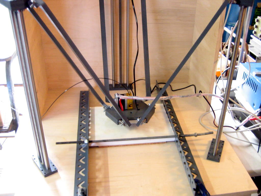
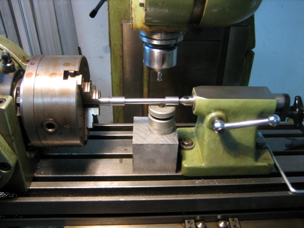
Second test run with fixed bed. The head bed is only connected to 5V from the ATX PSU t dump some amps. Wiko Spray Adhesive is applied to the print bed to make the parts stick.
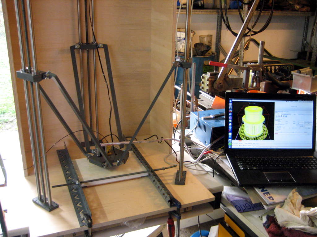
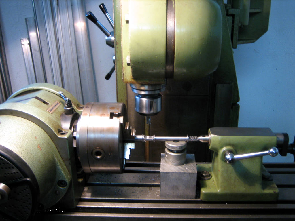
Another picture of the setup
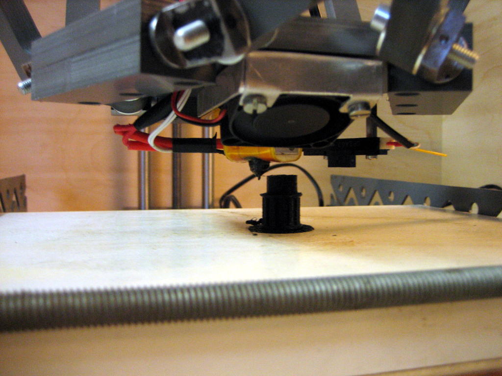
Second part is finished.
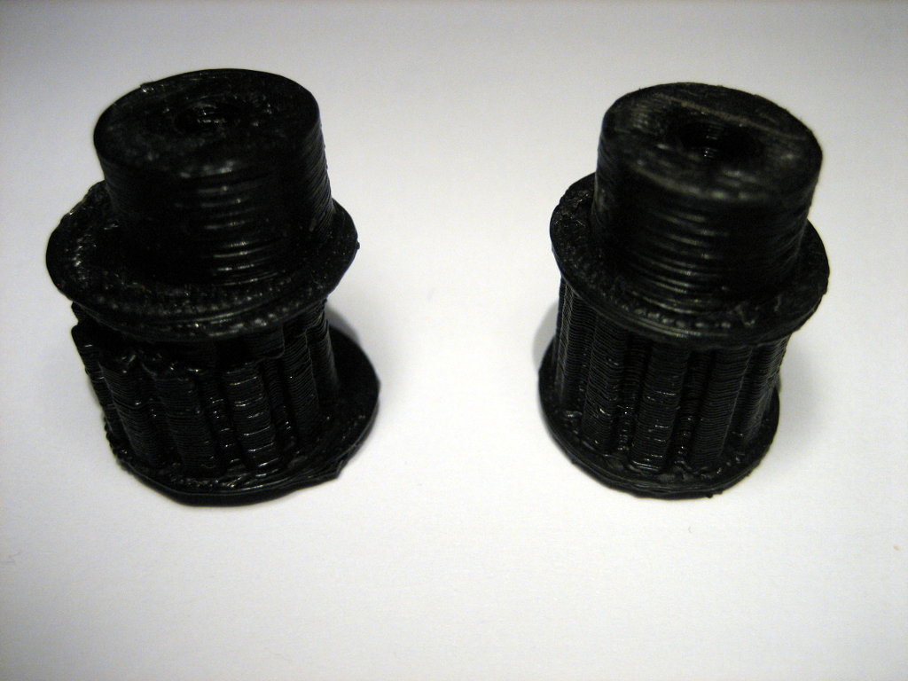
The first part on the left was printed without a mounted headbed. And FAILED! The part on the right is the second attempt. It looks promising. But the gemoetry still needs some callibration. Parts are made from PLA printet at 195°C with 0.4mm nozzle and 0.25mm layer hight. Print time was approx 1.5h.
Construction and Building
The Plan

Rendering of the 3D Printer
Milling of complex axle to conntect the diagonals to the sliders and platform. This part took the longest to make and six parts are needed for one printer.
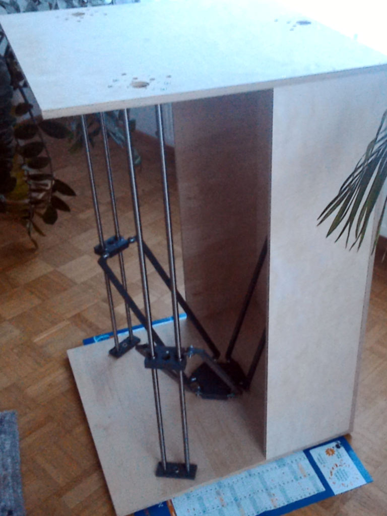
Some images of the partly assembled printer. Lead screws, endstops and extruder have not been assembled.
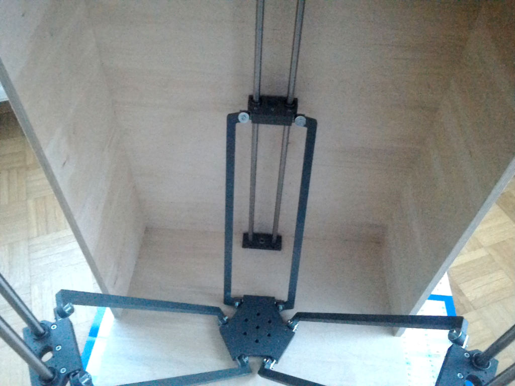
Detail of the platform for the extruder.
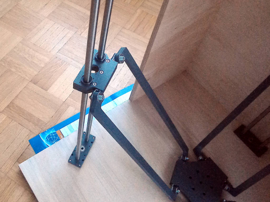
Detail of one slider.
Buildarea
Diameter: 400mm
Height: 500mm
BOM
| Pos. | Description | # |
|---|---|---|
| 1 | Ball Bearing 626ZZ | 3 |
| 2 | Bearing Plate Plastik 100x40x10 | 6 |
| Screws + Washer M4x20 | 24 | |
| 3 | Extruder | 1 |
| 4 | Guides D12x1000 | 6 |
| 5 | Heatbed | 1 |
| Screws + Washer M3x5 | 4 | |
| 6 | Housing Top Wood 640x660x15 | 1 |
| Housing Bottom Wood 640x660x15 | 1 | |
| Housing Back Wood 640x1000x15 | 1 | |
| Housing Side Wood 250x1000x15 | 2 | |
| 7 | Joint Axle Steel D16x116 | 6 |
| Screws + Washer M5x20 | 12 | |
| Spacer Sleeve D8xd5x10 | 12 | |
| 8 | Lead Screw M8x1000 | 3 |
| Coupling Steel D12x27 | 3 | |
| Nut M8 | 3 | |
| 9 | Linear Bearing | 6 |
| Screws + Washer M3x15 | 12 | |
| 10 | Link Plastik 420x40x10 | 6 |
| 11 | Stepper Motor | 3 |
| Screws + Washer M4x15 | 6 | |
| Motor Adapter Board PCB | 3 | |
| Screws + Washer M4x20 | 12 | |
| 12 | Nut (for Lead Screw) | 3 |
| Screws + Washer M3x10 | 6 | |
| 13 | Platform Plastik D85x10 | 1 |
| Platform Top 72x25x10 | 3 | |
| Screws + Washer M4x20 | 9 | |
| 14 | Bed Level Sensor SharpGP2A26 | 1 |
| Screws + Washer M2,5x25 | 2 | |
| 15 | Slider Top 90x55x10 | 3 |
| Slider bottom 90x55x10 | 3 | |
| Screws + Washer M4x10 | 9 | |
| 16 | End Stops TCYS5201 | 3 |
| Bracket L-Profile 30x12x16 | 3 | |
| Screws + Washer M3x15 | 6 | |
| 17 | Controller Arduino + RAMPS 1.4 | 1 |
| ATX PowerSupply 240 W | 1 | |
| Electronic Housing | 1 | |
| Power Board PCB | 1 | |
| Frontpanel | 1 | |
| Sub-D-Cabel 2m | 3 |
All measurements are in mm.
Extruder
3D Drucker Print Head Extruder Thermistor MK8 with 0.2mm, 0.3mm and 0.4mm Nozzle for RepRap.
Extruder specification:
- Nozzle Flow Rate: about 24cc/h
- Movement Shaft Speed: 10-100mm/s
- Normal Working Temperature: 190°C-250°C
- Max Temperature : 280°C
- Extrusion Nozzle : 0.2mm, 0.3 mm and 0.4 mm
- Thermistor: 12V 3950 100k NTC, accuracy 1%
- Cooling Fan Operating Voltage: 12V DC
- Heating Rods: 6mm, 12V, 40W
- Print Material: ABS, PLA
- Compatible With 1.75mm Filament
Motor specification:
- Model: 42HS40
- Wire Length: 20cm
- Stepping Angle: 1.8°
- Phase Current: 1.7A
- Phase Resistance: 2.5Ohm
- Phase Inductance: 4.2mH
- Motor Torque: 0.5NM
- Net weight: 402g
Note: heating nozzle 12V, the normal operating temperature 190°C-230°C maximum temperature does not exceed 280°C high temperature easy to damaged material.
Wiring:
- Red cable: Heating rod
- White cable: Thermistor
Ramps 1.4
http://www.reprap.org/wiki/RAMPS_1.4
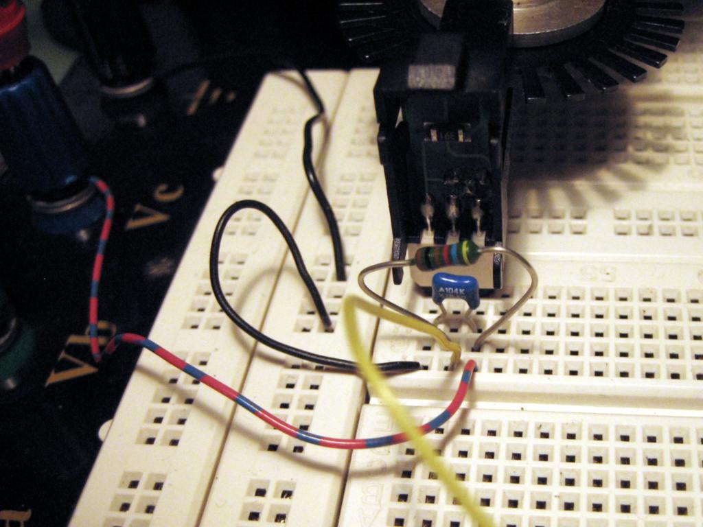
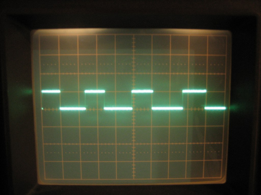
DRV8825 driver module
The DRV8825 stepper motor driver carrier is a breakout board for TI’s DRV8825 microstepping bipolar stepper motor driver. The module has a pinout and interface that are nearly identical to those of our A4988 stepper motor driver board, so it can be used as a higher-performance drop-in replacement for those boards in many applications. The DRV8825 features adjustable current limiting, overcurrent and overtemperature protection, and six microstep resolutions (down to 1/32-step).
It operates from 8.2-45 V and can deliver up to approximately 1.5 A per phase without a heat sink or forced air flow (rated for up to 2.2 A per coil with sufficient additional cooling).
Simple step and direction control interface:
-
Six different step resolutions: full-step, half-step, 1/4-step, 1/8-step, 1/16-step and 1/32-step
-
Adjustable current control lets you set the maximum current output with a potentiometer, which lets you use voltages above your stepper motors rated voltage to achieve higher step rates 45 V maximum supply voltage
-
Built-in regulator (no external logic voltage supply needed)
-
Can interface directly with 3.3 V and 5 V systems
-
Over-temperature thermal shutdown, over-current shutdown, and under-voltage lockout
-
Short-to-ground and shorted-load protection
-
4-layer, 2 oz copper PCB for improved heat dissipation
-
Exposed solderable ground pad below the driver IC on the bottom of the PCB
-
Module size, pinout, and interface match those of our A4988 stepper motor driver carriers in most respects
Calibration:
Uref = Imot * 0.5
Messure Uref between potentiometer and GND.
Power Board
The Power Board has connectors for a standart ATX power supply and outputerminals to connect the different voltages to Ramps 1.4 board. The Arduino and Ramps can be mounted on the Power Board. The Ramps power on feature is also supported.
Motor Board
The Motor Board connects one steppermotor and to endstops to Ramps 1.4 Board or to an ISEL Stepper Driver.
Optical Sensors
Planned use as endstop.
Software
Firmware for RAMPS 1.4: Marlin
http://www.reprap.org/wiki/Marlin
Slicer and host Software